Quantcast
Channel: iMechanica - ABAQUS
Viewing all 255 articles
Browse latest View live

UMAT Non linear Viscoelasticity - Algorithm verification?

$
0
0
AttachmentSize
Copy_17_Haj-Ali.pdf408.4 KB
algorithm.pdf200.5 KB

Hello everybody,

           My task is to write a UMAT for Non-linear Viscoelasicity based on Schapery's model in ABAQUS. I have coded the routine, but I am still not able to predict correct response. I tried to debug it as much as I can. I understand that it would be difficult for anybody to understand my code. So, I have attached a flowchart (pdf) of the whole algorithm that I follow. It would be nice if you could check that and correct me if I am wrong.

Thanks in advance for your time and consideration

Regards

Shree

PS. I have also attached a copy of the paper that I am referring for the model. 


Welding analysis with Abaqus using amplitudes

$
0
0

Hello everyone,

I know that there are some posts about welding simulation with Abaqus and i looked at them already and I couldn't find something similar to my problem. I model a moving heat source with amplitudes and sets in Abaqus/Standard. I define body heat flux loads and give them amplitudes and magnitudes. The model is meshed with DS4 shell elements. The problem is that ater the simulation it is visible (with temperatures visualization) that the heat flux is not inputed linearly in the model. I mean to say that there is no linear movement of the heat source that is typical to welding, although all fluxes are inputed at the specified time. I'm uploading three pictures so you can see what the problem is. Picture with time 14.73 shows one active flux. Picture with time 15.42 shows the time in which active flux shuts down and a new one starts (visible bigger red area, not linearly moving flux). Picture with the time 17.47 shows one active flux after the previous one shuts down. Please help as soon as you can because this is a part of my master thesis and I have limited time.

Thank you!

AttachmentSize
Time_14.73.png32.13 KB
Time_15.42.png29.88 KB
Time_17.47.png32.18 KB

How to obtain the Force-Indentation depth curve of nanoindentation FEA?

$
0
0

Dear all experts,

I did FEA of nanoindentation with using Abaqus and considered displacement of reference point (RP) on the indenter as a punching tool. Moreover, Abaqus/Explicit method  was applied for solving problems.

But I do not know how to plot Force-Indention depth curve via FEA with using Abaqus.

Any suggestions would be greatly appreciated.

Amin


Advanced Biomedical Modeling Seminar & Workshop, Irvine, CA, Apr 19

$
0
0

Irvine Workshop

Date: Tuesday, April 19, 2016

Venue: University of California Irvine, Irvine, CA 92697

Fee: Free to attend

Register here

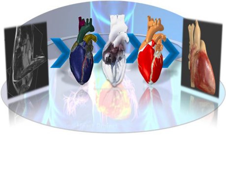
Advances in medical imaging have opened up a new era of engineering requiring multiphysics simulation of human and other natural forms (known as biomimicry). With this new, non-CAD driven simulation market poised to grow rapidly, advanced methods have been developed to rapidly take conventional medical image data and convert it directly to 3D meshes, allowing easy import into solvers such as Abaqus to optimize their use for medical device design, medical diagnostics and 3D printed prostheses.

This full-day seminar and workshop will showcase the seamless integration between the 3D image processing and mesh generation tool ScanIP by Simpleware and SIMULIA’s Abaqus Multiphysics FEA. The morning will feature state-of-the art technical presentations from leaders in the biomedical engineering field followed by an afternoon of hands-on training with the software.

Why attend?

This event is ideal for all engineers and researchers in the medical device, healthcare or consumer oriented high tech industries interested in using realistic human models in their design, evaluation and testing process. Over the course of the day, they will not only gain an understanding of the progress in this developing field, but also learn the complete workflow to take a heart model from start to finish, beginning with 3D Scans and ending with a dynamic beating heart model. Knowledge of ScanIP or Abaqus is useful but not required.

Agenda:

8:00 – Noon   Biomedical Simulation Symposium

Noon- 1:00   Lunch (Provided)

1:00 – 4:00   Hands-on Workshop

Registration:

The workshop is free but pre-registration is required as places are limited.

Structural simulation position @ Bosch

$
0
0

Robert Bosch Engineering and Business Solutions is a branch of Robert Bosch (Fortune 500) is seeking a Senior Engineer for its Simulation team in Ho Chi Minh city, Vietnam. Only applicable for Vietnamese candidate or candidate can work in Vietnam

Senior structural simulation engineer

Requirements:

·         BSc, MSc or PhD in Mechanical Engineering, Computational Engineering, Maths or related fields

·         Strong knowledge of continuum mechanics, structural mechanics, Finite Element Analysis (FEA)

·         Practical experience with FEA software: Ansys Workbench, Ansys mechanical, Abaqus, Nastran, COMSOL, etc.

·         Good knowledge in meshing tool: Hypermesh, Ansys meshing, Abaqus/CAE, etc.

·         Handle simulation tasks independently

·         Be able to perform quality-check for simulation task and guide junior member effectively

·         Willing to learn new simulation aspects, simulation tasks, products

·         Highly enthusiastic, motivated & result oriented

·         Be able to work in a collaborative team and possess high team spirit

·         Good discipline

·         Good communication skills

·         Advance in MS office

·         Advance level in English both speaking and writing

·         Willing to travel to India, or other countries for the short period

·         Knowledge in linear/non-linear analysis, fatigue analysis, vibration analysis  is desirable

·         Intermediate programming skill (Matlab, C++, VBA, Fortran, Python, etc.) is desirable

·         Knowledge in CAD tools (such as Pro-E, Catia, SolidWork, etc.) is desirable

·         Knowledge in Japanese/German is desirable

·         Be able to work with linux is desirable

 Please send your CV to me: kadung@gmail.com
Lunch & Learn Seminar with Simpleware and SIMULIA, April 27 2016

$
0
0

Date: Wednesday, April 27, 2016

Time: 10:00 am EDT 

Venue: SIMULIA Great Lakes Region, 3200 Greenfield Road, Suite 310, Dearborn, MI 48120

Organisers: SIMULIA Great Lakes Region, Ms Lynne SUNDBERG

3D image-based modelling from MRI, CT and other modalities is becoming crucial to the Aerospace, Oil & Gas, Consumer Products, Automotive and Medical Device industries. This Lunch & Learn will outline how to go from scanned image to model and simulation in Simpleware and SIMULIA Abaqus software. We will discuss using Simpleware software to generate robust surface (STL, NURBS) and volumetric (FE) meshes from 3D image data for direct import to Abaqus for simulation. Case studies will be provided, as well as a hand-on demo showing the functionality of the Simpleware software environment.

Who should attend?

This lunch & learn seminar is aimed at those interested in 3D reconstruction from image data (as obtained from CT, FIB-SEM, MRI etc.) to generate models for visualization, measurement, and/or FE simulation in Abaqus.

During this session you will learn the basics of using Simpleware software, including:

  • Importing and working with different types of 3D image data
  • Visualizing and segmenting data to identify regions of interest
  • Measuring and analysing images (dimensions, porosity statistics…)
  • Generating high-quality meshes for import and simulation in Abaqus
  • Typical workflows and applications for using 3D image data

Agenda:

10:00 am Welcome & Introduction

Saurabh Bahuguna, SIMULIA Director, Technical Sales, Dassault Systemes

10:15 am Simpleware Overview

Kerim Genc, Technical Sales Manager, US & Canada, Simpleware

11:15 am Hands-on Demo

12:00 pm Lunch & Discussion

1:00 pm Free Hands-On Time

Registration:

The workshop is free but pre-registration is required as places are limited.

Register here

ABAQUS, partitioning an edge

$
0
0

Hello Everyone,

Does anyone knows how it is possible to partition an edge in one step with multiple points (like multiple datum points or multiple parameter values)? I know how to partition one edge one by one. The problem of doing it one by one is the amount of time that it takes to do that. For example if I want to put 50 points on one edge I have to pick that edge 50 times and partition it, which takes a lot of time.

I am doing the whole process by scripting with Python so I would be glad if the solutions are in scripting format (I am using ABAQUS 2016).

Thanks,

Navid

Simplified slip-bearing action by using stop ellement in Abaqus

$
0
0

Hi
can anyone please advise me to define connector ellements with following details:
Using rigid plastic CARTESIAN element and a STOP element in parallel and The connector behaviour must be:
1- rigid up to the slip force limit Rn
2- slip at the bolts up to ±1 mm at constant force Rn
3- rigid bearing hardening


AttachmentSize
1234.JPG22.9 KB

Modeling with line spring elements to find failure pressure of steam generator tube

$
0
0
AttachmentSize
Capture.PNG97.86 KB

Hello, All
I am trying to model steam generator tube of length 110 , radius 11mm, thickness 1.27mm. It has 2 axial cracks of length 6.35mm. length between 2 cracks is 0.254mm. 

As line spring elements cannot be created using Graphical user interface I first need input file. So I modelled the tube with shell elements S8R without any crack (once this model will run I will get input file and can modify it). As per paper which I am following the fracture coalescence pressure is 60Mpa means at this pressure J integral exceed the critical JIc. 

**Material Property**
Material is Alloy 600.
Material property (Entered in ABAQUS): Elastic Modulus : 200 Gpa, Poission ratio : 0.3 
Plastic property : Stress(MPa) Strain(mm/mm)
300 0
512 0.09274
687 0.178865
840 0.2582
946 0.33177
1125 0.5
1700 1.05
When I tried to run model WITHOUT CRACK (just simple cylindrical tube, length 55mm with end cap, quarter symmetry). At 30 MPa I didn’t get any warning. But at 60 Mpa I am getting warning that strain increment has exceeded 50 times the strain to cause first yield at xxxx points. Moreover I looked in job diagnostic so it shows that one node have numerical singularity.

What should I do to troubleshoot this warnings?

Pressure Difference Calculation in ABAQUS

How do I rectify an error regarding memory storage when I generate substructures in ABAQUS?

$
0
0

I have been trying to generate a substructure in ABAQUS for a big diameter roller bearing. I have used two reference points, one each for inner and outer raceways to couple the inner and outer raceway surfaces. I have two steps in the analysis. The first step is Frequency followed by Substructure generation step. The analysis runs fine till the end of first step and calculates the eigen frequencies. When the second step starts, following error message appears.

" Element 439473 requires more than 2GB of memory for storage"

Element 439473 is just a point on the outer raceway and it is not used in any of the couplings. I have used continuum distributing couplings for coupling the reference points and the raceway surfaces. Following error also pops up after the element error.

***ERROR: An attempt to access admc buffer has failed. Any help would be truly appreciated.

Thanks in Advance.

Renganathan Sekar


Applying a moving pressure and traction in Abaqus

$
0
0

Hello all,

I have applied a moving ellyptical hertzian pressure load on a surface using a DLOAD which works, but I also need the traction load which is the multiplication of this pressure with a friction coeffcient.

Does anybody have any clue how to do it? Directly through abaqus or inside the same DLOAD?


Kind regards,

Omid

UMAT for Zener model and Kelvin-Voigt model

$
0
0

Dear iMechanica community,

you can find the UMAT-implementation of a Zener model, i.e. a Maxwell model parallel to a spring, in my PhD thesis:

“Upsetting and Viscoelasticity of Vitreous SiO2: Experiments, Interpretation and Simulation“
Technische Universitaet Berlin, Germany, 2006
https://depositonce.tu-berlin.de/handle/11303/1574
http://dx.doi.org/10.14279/depositonce-1277

The footnote g on page 33 is clearly insufficient. The theory is written up in 'Theorie-Alexandru.pdf' and is like the one in:
author: Rudolf Trostel
titel: Mathematische Grundlagen der Technischen Mechanik III, Materialmodelle (in German, translation: Mathematical foundations of Technical Mechanics III, material models)
publisher: Vieweg+Teubner Verlag, Germany, 1999
ISBN: 978-3-528-03912-7 (Print), 978-3-322-93842-8 (Online)

The table of contents of this book is available from
http://link.springer.com/book/10.1007/978-3-322-93842-8
Clicking on the chapiters "Maxwell-Koerper" or "Kelvin-Koerper" will open the first page of the respective chapter.

Further, I post a follow-up to my PhD thesis which derives in an analogous procedure the implementation of a UMAT for a Kelvin-Voigt model.

Sincerely

Frank Richter

UMAT for MAZAR's Concrete Damage Model

$
0
0

Hello All,

I am working on stochastic upscalling of damage in concrete microstructure. Can someone provide a UMAT for Mazar's damage model or any resource to help me create UMAT on my own.

Thank you.


Vasav Dubey

Texas A&M University

Texas, USA


Is it possible to solve buckling in Abaqus with only residual stress defined as predefined load?

$
0
0

Hi Sirs,

As title, I wondering if the problem can be solved with only material residual stress but no other external load applied?

After several trials, Abaqus returns message
"MASS OR DIFFERENTIAL STIFFNESS MATRIX IS COMPLETELY NULL. THE EIGENPROBLEM CANNOT BE SOLVED. IN A *BUCKLE ANALYSIS THE MOST LIKELY CAUSE IS THAT A NONZERO LOADING PATTERN WAS NOT SPECIFIED VIA *BOUNDARY, *CLOAD, *DLOAD, ETC,. SEE Eigenvalue Buckling Prediction IN THE ABAQUS/STANDARD USERS MANUAL"

However, in my case, no external load but only residual stress within materials and buckling does occur.

Any expert has suggestions or experience on this? Very thanks.

FELIPE


DLOAD, element deletion, new active load surface

$
0
0

Dear all,

I am actually engaged in the decision of geological problems. So we have a some model with the soil disk, there is a circular hole in the centre, witch has initial pressure at the first time(a modelling of the soil injection with the polymer solution). How can I recalculate by the subroutine DLOAD a normal pressure inside of the circular hole in the soil model if a nearest FEs were failed. Failure criteria is given by Mohr Coulomb criterion (https://en.wikipedia.org/wiki/Mohr%E2%80%93Coulomb_theory).


This is predictable behaviour : predict.png
This is unpredictable behaviour : unpredict.png
This is my subroutine: sand_v9si-02.for_.txt
This is my model: Geo-si-07.inp_.txt

This is my question: Question.pdf

Many thanks for any help 

AttachmentSize
predict.png23.53 KB
unpredict.png24.3 KB
sand_v9si-02.for_.txt8.47 KB
Geo-si-07.inp_.txt312.04 KB
Question.pdf636.29 KB

ABAQUS, DLOAD, new active load surface, element deletion

$
0
0
AttachmentSize
predict.png23.53 KB
unpredict.png24.3 KB
sand_v9si-02.for_.txt8.47 KB
Geo-si-07.inp_.txt312.04 KB
Question.pdf636.29 KB

Dear all,

I am actually engaged in the decision of geological problems. So we have a some model with the soil disk, there is a circular hole in the centre, witch has initial pressure at the first time(a modelling of the soil injection with the polymer solution).

How can I recalculate by the subroutine of DLOAD a normal pressure inside of the circular hole in the soil model if a nearest FEs were failed?

This is my question: Question.pdf

Failure criteria is given by Mohr Coulomb criterion (https://en.wikipedia.org/wiki/Mohr%E2%80%93Coulomb_theory).


This is predictable behaviour : predict.png
This is unpredictable behaviour : unpredict.png
This is my subroutine: sand_v9si-02.for_.txt
This is my model: Geo-si-07.inp_.txt


Many thanks for any help 

crack propagation in Abaqus (VCCT) with remeshing

Abaqus VDLOAD/DLOAD

$
0
0

I'm using the ABAQUS DLOAD subroutines, and I'm curious what the dimensions of the 

volume distributed body load should be. 


I understand ABAQUS uses [LT-2] for GRAV body loads. However, I'm curious if the 

units for BZNU acting over a volume should be [density]*[acceleration] or just

[acceleration].


Thank you,

Anirban

ABAQUS - Stress Intensity Factor for Single Radial Crack in Thick Walled Cylinder

$
0
0

Hi,

I am trying to analyze the stress intensity factor (SIF) using contour integral of a 2D thick walled cylinder under plane stress with different wall ratios under internal pressure loading only and a single radial crack of varying length in Abaqus.

The wall ratio (inner & outer radius) I am interested in modelling is of ratio 6 (i.e. for inner radius of 1, outer radius is 6).

I have modelled ratios from 1-6 with crack length varying from 0.1-0.9 of the wall thickness. (i.e. for ratio 3, the wall thickness is 2, hence the crack varies from 0.1-0.9 x 2).

What I have discovered:

  • for ratios (<5) the SIF at the crack tip monotonically increases as crack extends from 0.1-0.9 of the wall thickness.
  • for ratios (>5) the SIF at the crack tip decreases as crack length extends from 0.1-0.6, and increases later on from crack length 0.7-0.9.
  • the stress distribution for ratio (<5), the max stress always occur at the crack tip leading to the increase in SIF as crack extends.
  • the stress distribution for ratio (>5), the max stress do not always occur at the crack tip but at the sometimes at the inner wall leading to a decrease in SIF but later on occurring at the crack tip as crack extends.

I have compared my results obtain with published literature for ratios (1-3) and are in good agreement (less than 2%). But there is no published data for ratios (>3) and I require the results for larger ratios.

I believe thre isn't any issue with my modelling procedure since I obtained results that are in good agreement for ratios (1-3) but however, I cannot explain why the issue of maximum stress not occurring at the crack tip for larger ratios. I applied a triangular mesh at the crack front converging at the crack tip and quad mesh on the remaining geometry.

So my questions are:

  1. Has anyone ever encountered a situation where SIF decreases with increasing crack length even though all other parameters remained the same?
  2. Is a decrease in SIF unreasonable? Because, in theory it should increase with crack length when stress remain constant.
  3. Why is the max stress not always occurring at the crack tip in the modelled and instead on the inner wall surface for ratios (>5).

Any advice/input/recommendation would be greatly appreciated. I can upload my model if required and can also be contacted through email at ianlau11@gmail.com

Kind regards,

Ian


Viewing all 255 articles
Browse latest View live